ビーズミル:ビーズミルの原理、湿式分散・粉砕、ナノ分散について
1. Recent needs for nanoparticle dispersion
In recent years, nanomaterials have been applied to the advanced materials and chemical industries. Some portions of them are processed by bead mills that utilize microbeads finer than 100 micrometers. The microbead mills have contributed to improvements in qualities and performances of industrial products using nanomaterials, such as the resolution of liquid crystal displays, micronized electric parts of mobile phones, and the transparency of sunscreen. Lately finer nanoparticles have been required for further improvements in qualities of the nanomaterials. It has been, however, increasingly difficult to disperse nanoparticles finer than 100 nanometers without significant crystal damages, since the finer they are, the more fragile they are. The nanoparticles are easily damaged by the impacts of microbeads even they are finer than 100 micrometers. Note that the crystal damages of the nanoparticles result in re-agglomeration, loss of crystal soundness, and gelling of slurry. Required for the modern nanomaterial processing were, therefore, new bead mill technologies that materialized dispersion of nanoparticles with minimized crystal damages by controlling the impact of beads, and also with homogeneous agitation.
2. Bead mills for low-damage and homogeneous nano dispersion
Since microbeads finer than 100 micrometers are used for dispersing nanoparticles, a bead mill equipped with a centrifugal bead separator is applied to processing using the microbeads. It is because choking of the slurry does not occur in the bead separator, but on the contrary, it occurs in other types of bead separators.
However, the conventional microbead mills do not satisfyingly correspond to the requirement of dispersion of the fragile nanoparticles. In the conventional microbead mills, slow rotation for getting the moderate agitation results in low centrifugal force for the bead separation since the rotor and the agitator are fixed on a single driving shaft. In addition, finer microbeads require a higher centrifugal force for separation. The microbeads leak from the conventional bead mills when the rotation slows down to soften the impacts.
Thus, new technologies are required for dispersing such fine and fragile nanomaterials without significant crystal damages. To respond this need, Hiroshima Metal & Machinery developed a new microbead mill equipped with a dual-axial driving mechanism for dispersing nanoparticles with low crystal damages (Dual Apex Mill (DAM)). The agitator and the bead separator are driven independently by two axes. The mechanism allows low speed agitation and highspeed rotation of bead separation at the same time. This model has been applied to many advanced fields of slurry treatment for dispersing nanoparticles, such as processing barium titanate for ceramic capacitors, pigment slurry, etc.
In addition, most lately requirements of dispersion of nanoparticles with low crystal damage have been more intense for producing state-of-art nanoproducts. Thus, Hiroshima Metal & Machinery recently developed the newest and most advanced model, Ultra Apex Mill Advance (ADV), that is specialized in dispersion of nanoparticles with ultimately low crystal damages. This model also provides a uniform particle size distribution.
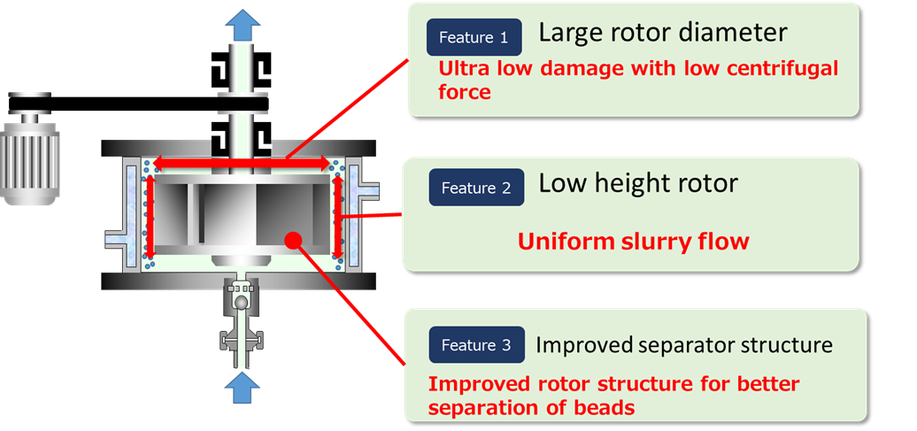
The ADV employs a multifunctional rotor that has functions of an agitator and a bead separator in a single structure. The rotor is featured as large rotor diameter producing low centrifugal force to reduce the impact, low height for uniform slurry flow, and good capability of bead separation corresponding to low centrifugal force. It is applicable to advanced nanomaterials, such as 100 nanometer class barium titanate and nano metal-complex pigments.
3. Low damage nanoparticle dispersion by microbeads and low impact
3.1 Dual Apex Mill/DAM – low impact of beads and superior bead separation
Features
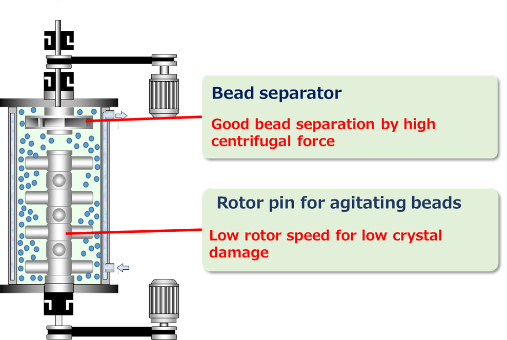
For dispersion of nanoparticles with low crystal damages, it is necessary to use microbeads as fine as 50 micrometers, and to agitate the slurry-bead mixture moderately. Therefore, the microbead mill should have both good capability of microbead separation and moderate agitation at the same time. Slow rotation of the agitator results in moderate agitation in the conventional microbead mills, however it results in decrease in the centrifugal force for bead separation. It is because the agitator and the bead separator are fix to a single driving shaft. Therefore, the microbeads easily leak from the mill.
The DAM solves this problem by adopting a dual-axial driving mechanism revolving the agitator and the bead separator by two shafts. In the conventional bead mills equipped with centrifugal bead separator, the rotor speed is limited above 6m/s, since slow rotation results in bead leakage. Contrarily, the lowest rotor speed of the DAM is 2m/s. It is because even the agitating rotor revolves at low speed, the separator does at high speed. The low speed rotation of the agitating rotor enables the DAM to reduce the crystal damages caused by strong bead impacts. The DAM has been employed by a number of customers who process nanomaterials avoiding crystal damages, such as barium titanate for the ceramic capacitors and metal-complex pigments for the liquid crystals.
Two models are available, a single motor coaxial type for mass production with fixed rotor speeds and a dual driving axil type for operation requiring frequent speed change.
Example of DAM treatment:
Dispersion of titanium oxide (coating material for UV cut glass
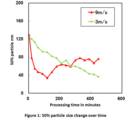
Slurry of titanium oxide (primary particle size: 15 nanometers) was dispersed to examine performance of the DAM to reduce the crystal damages in this experiment. Fig. 1 shows changes in mean diameter of the secondary particles at the rotor speeds of 3 and 9 m/s using 50 micrometer beads. The mean diameter rapidly dropped to 40 nanometers in the first 120 minutes in the experiment of 9 m/s rotor speed, but after then, it rebounded to 80 nanometers. On the other hand, the mean diameter dropped gradually to 40nanometers in the experiment of 3 m/s rotor speed, and it did not rebound.
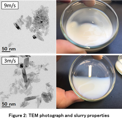
It was observed in the TEM photography of Figure 2 that the primary particles fragmented in a crumbly manner, and the fragments were re-agglomerated forming a large cluster in the experiment of 9 m/s rotor speed. The primary particles were shaved making fine fragments, which formed clusters. Contrarily, few fragments were observed in the TEM photograph of the experiment of 3m/s rotor speed. The primary particles were seldom shaved. These evidences show that the processing of the low rotor speed resulted in low crystal damages and good conditions of dispersion.
The slurry processed at the 3 m/s rotor speed was low in viscosity and light white, while that processed at the 9 m/s rotor speed was high in viscosity and muddy white. Thus, the property of the titania slurry processed in the treatment of 3 m/s rotor speed was appropriate to materials of the UV cut coating.
3.2 Ultra Apex Mill ADVANCE (ADV)
– Nanoparticle dispersion with low crystal damage and high homogeneity –
Features
Ultra Apex Mill Advance (ADV) is a bead mill that is optimized for “nanoparticle dispersion with ultimately low crystal damages.”. The ADV employs a state-of-art multifunctional rotor that enables nanoparticle dispersion with the lowest crystal damages in the HM&M’s lineup. The mill has a wide and low height agitation/bead separation rotor, which provides low centrifugal force for moderate agitation in the mill. The rotor has a capability of bead separation good enough for microbeads even under condition of the low centrifugal force.
The rotor has 4 features that make the mill different from others.
Feature 1 Multifunctional rotor; the rotor is basically a bead separator and is redesigned to have an agitational function that provides a uniform rotational flow.
Feature 2 Large diameter; the rotor that is large in diameter provides low centrifugal force to reduce the impact of beads.
Feature 3 Low height; small H/D (Height/ Diameter) prevents short pass of slurry and gives a uniform slurry flow in the mill.
Feature 4 High bead separating capacity; despite the centrifugal force is low, microbeads as fine as 30 micrometers are separated satisfactorily owing to the newly designed rotor with a good capability of bead separation.
As described above, since low impact force is given in the ADV even at a high rotor speed, the ADV provides a high frequency of contacts between beads and nanoparticles and low impact force to minimize the crystal damages of nanoparticles at the same time. Uniform distribution of agitational energy in the mill is also required for the microbead mills for dispersing fragile nanoparticles, as locally high impact force should also be avoided to minimize the crystal damages. Low height and straight agitating blades of the ADV’s rotor provide uniform agitational energy in the mill, so that low impact energy is given both entirely and locally. In addition, the low height rotor prevents short pass of the slurry making better uniformity of the slurry.
The ADV provides proper dispersing conditions to keep the sound crystals of barium titanate finer than 100 nanometers for the upcoming advanced ceramic capacitors, to maintain the particle shapes of nanometals for secondary battery’s electrodes, and to give a sharp size distribution of pigments for the highly transparent ink-jet inks.
Example of ADV treatment: Dispersion of Barium Titanate (material for MLCC)
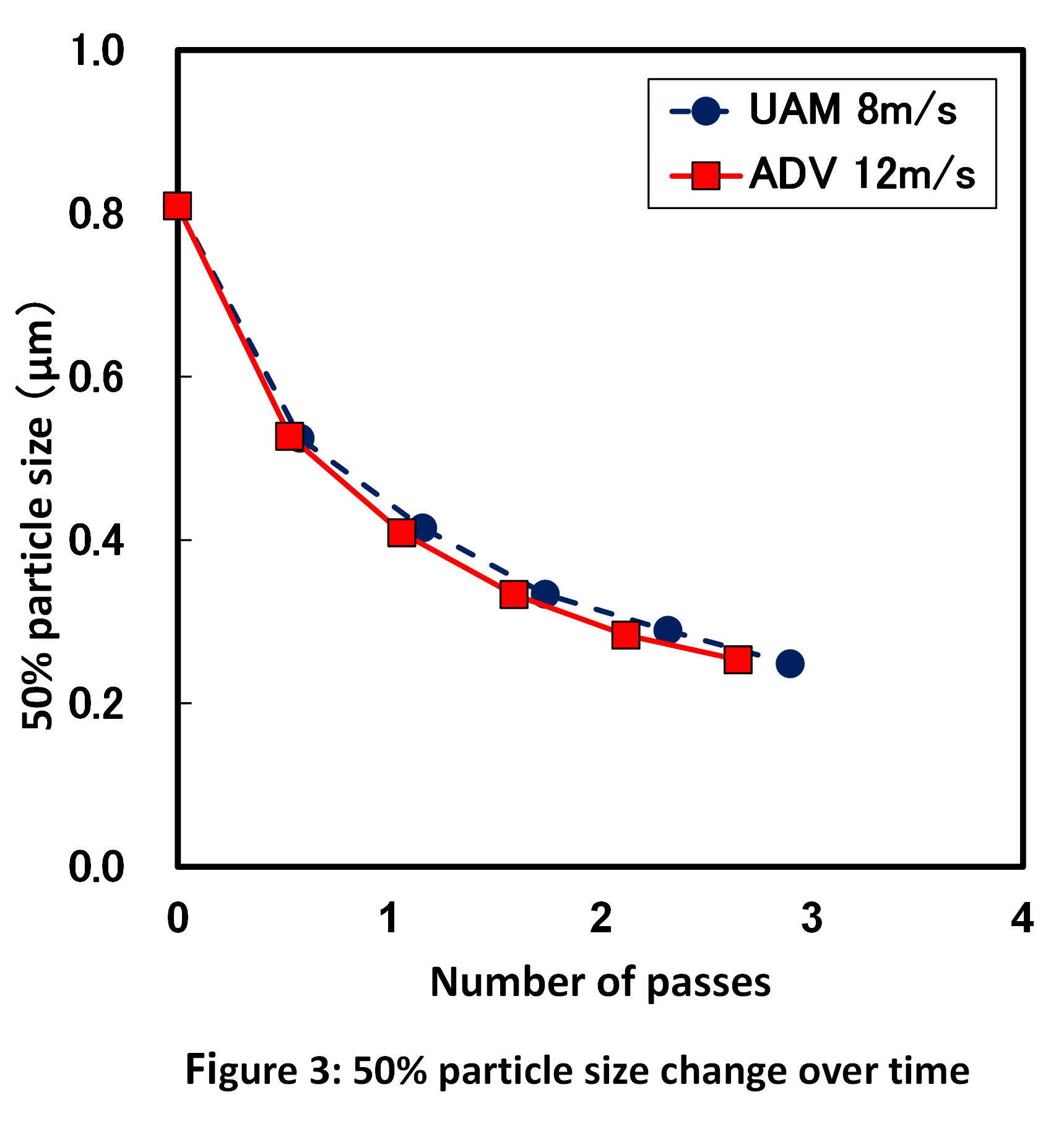
Slurry of barium titanate (primary particle size: 200 nanometers), which is a fragile nanomaterial, was treated to compare degrees of the crystal damages in the UAM and the ADV. The slurry was dispersed at 8 m/s rotor speed in the UAM and at 12 m/s rotor speed in the ADV using 30 micrometer beads. Centrifugal force of the ADV was lower than that of the UAM even though the rotor speed of the ADV was higher. It is due to the larger diameter of the ADV’s rotor.
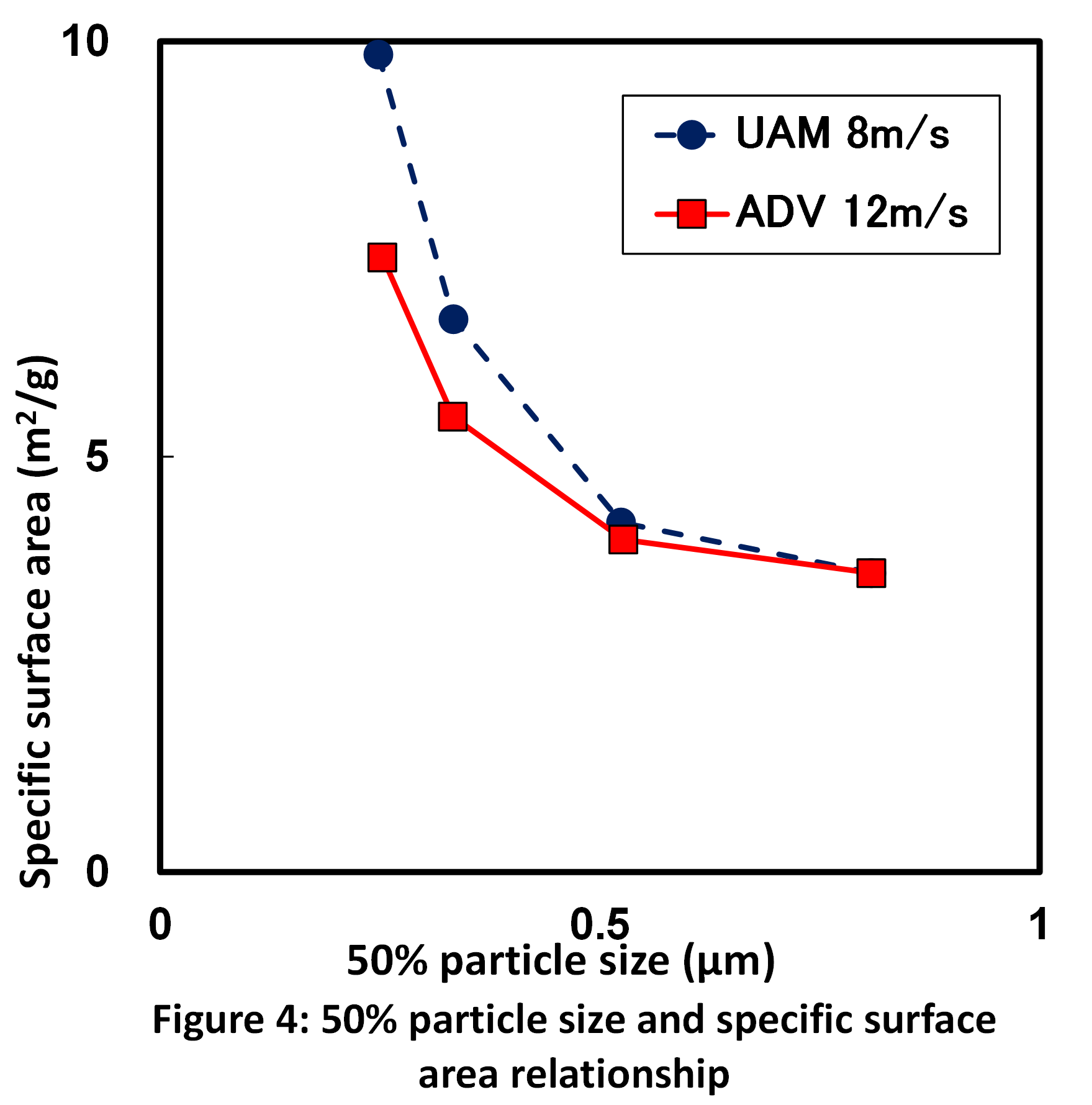
Changes in the mean diameters of the particles of the two mills are shown in Fig. 3. The rates of decreases in the mean diameters were the same for the two practices. To evaluate the crystal damages, the relationship between the mean diameter and the specific surface area of the dispersed nanoparticles was plotted in Fig. 4. The relationship shown in the graph is an indicator of fragmentation of the primary particles. When the primary particles are crushed into smaller fragments, the surface area increases.
The specific surface areas of the two mills increased with decreases in the mean diameters. During the early stage of dispersion, when the mean diameter went down from 0.8 to 0.5 micrometer, the specific surface areas of both mills changed slightly. It indicates that the secondary particles were dispersed without significant crystal damages in the period. When the mean diameter went smaller from 0.5 to 0.25 micrometers, the specific surface area of the UAM increased steeply as the mean diameter decreased, but that of the ADV did more slowly. It indicates that the crystal fragmentation of the ADV was fewer when the mean diameter was less than 0.5 micrometer.
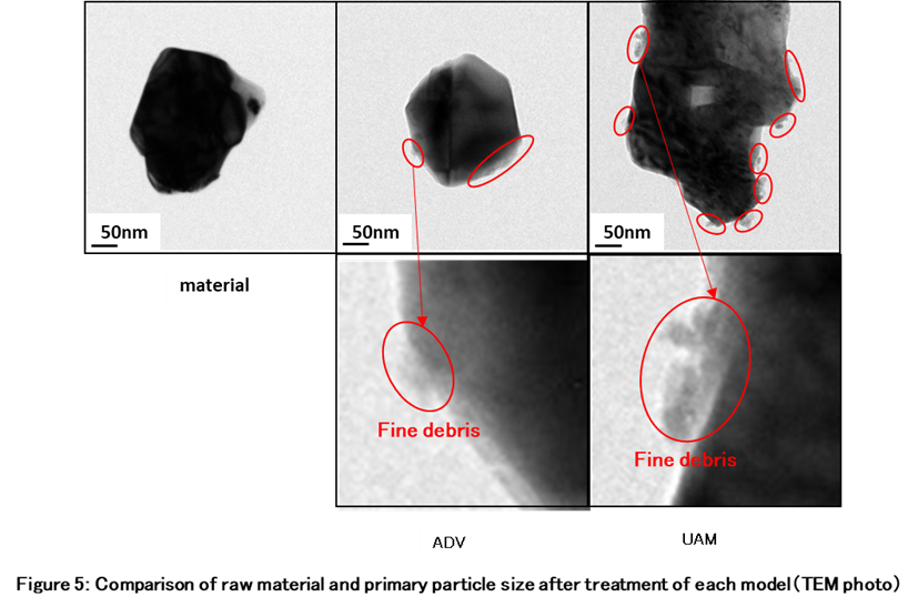
It is considered that the debris generated from the nanoparticles were a lot in the UAM and they adhered to the primary particles, resulting in stagnation of decrease in the mean diameter despite the primary crystals went finer. On the other hand, the stagnation was much lower in the ADV. The crystal damages on nanoparticles were lower and the condition of dispersion was better in the ADV.
The understanding of the result written above was confirmed by observation of the TEM photography of the primary particles processed by the two mills. As shown in the TEM photographs of Figure 5, several debris were on the primary particle processed by the UAM. The surfaces of the barium titanate particles were shaved down and chipped into the debris. They adhered to the primary particle. However, only few debris adhered to the primary particle processed by the ADV. The TEM photography observation shows that the ADV disperses fragile nanoparticles like barium titanate without significant crystal damages.
4. Example of treatments
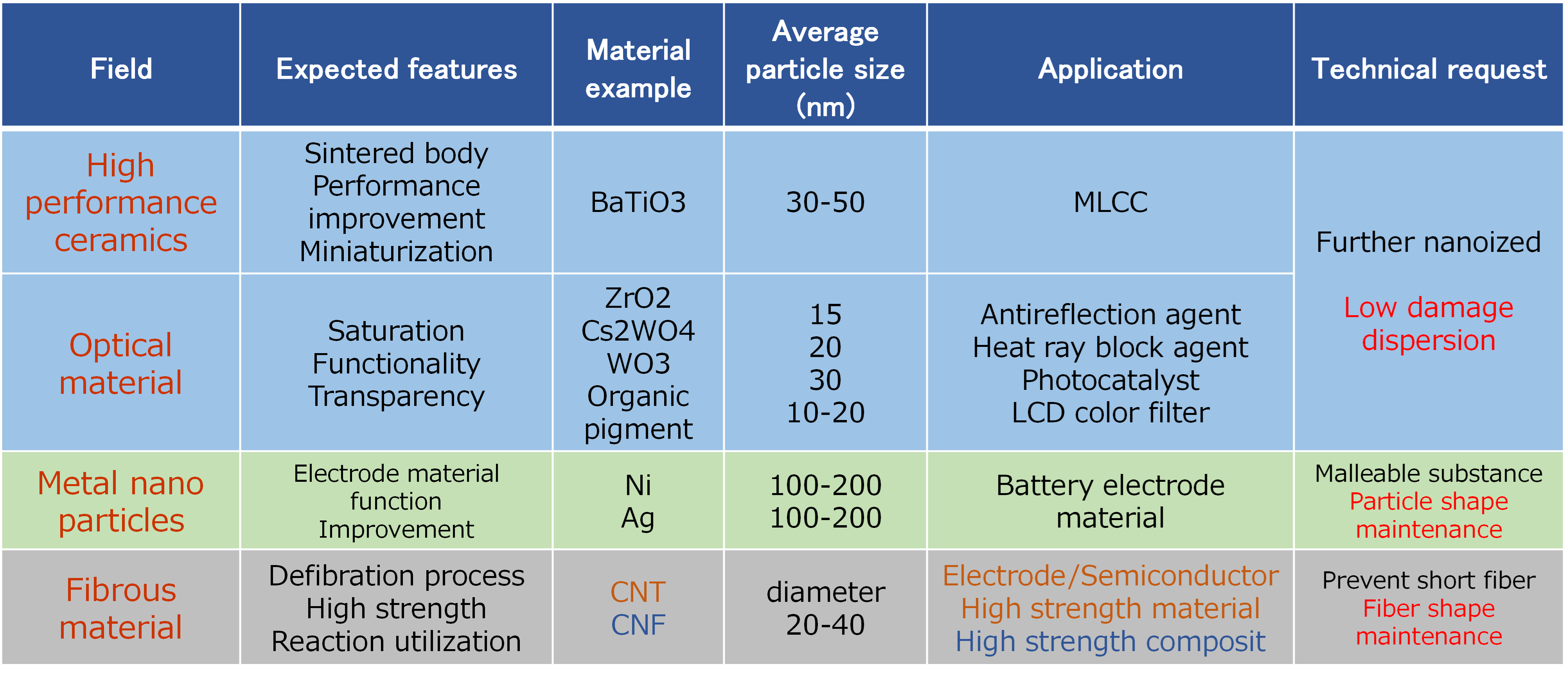
Table 1. Applications already applied
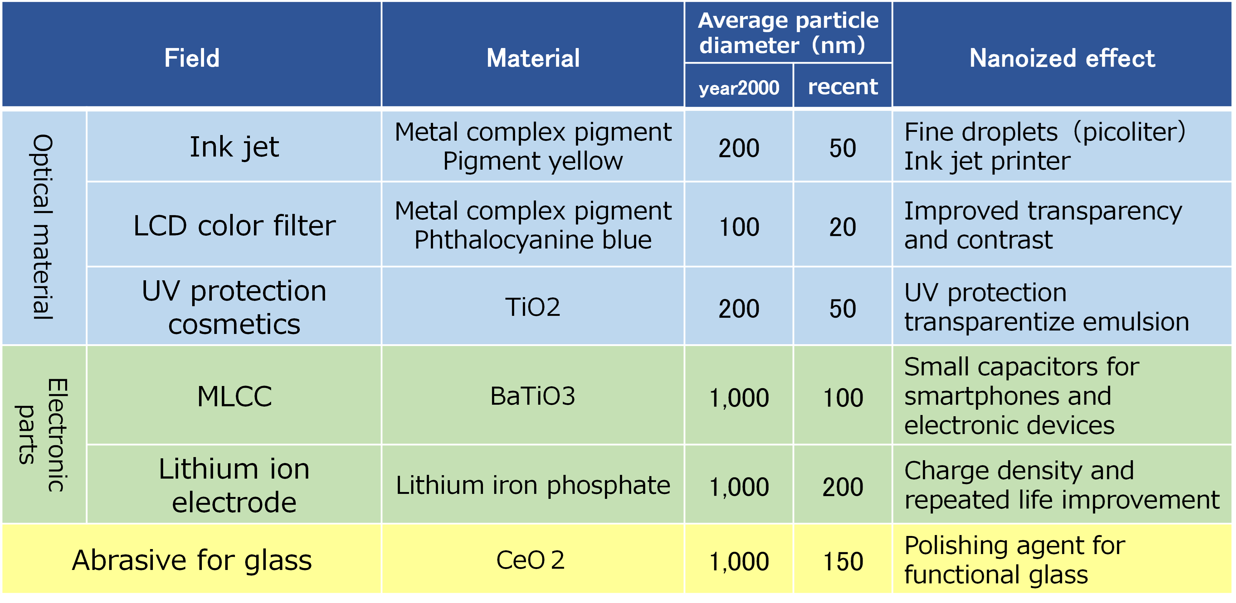
Table 2. Expected future adaption
